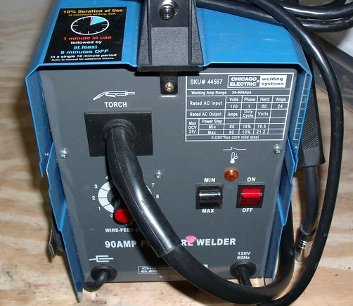
The welder power supply basically consisted of a transformer with two taps on the input (for two power levels), and that's it. The output of the transformer was about 28VAC. I played around with it, trying to weld 1/8" steel sheets in both butt joints and T-joints, but was disappointed by the lack of penetration, even at maximum power. From what I had read online, a DC power supply would produce better welds for wire feed welders, so I figured I'd try to convert my unit to DC.
Converting AC to DC is fairly straightforward. First, you rectify the AC into DC using diodes, preferrably in a bridge configuration. Next, you smooth the output using filter capacitors. Finally, you can use inductors to further smooth the load. I'd need to keep in mind the polarity; flux core welders are electrode negative, so the positive terminal went to the ground clamp, and the negative terminal went to the wire feed. MIG welders are typically the opposite (electrode positive).
I examined my dad's Miller MIG welder to get an idea of how much capacitance and inductance I'd want. His welder had about 120,000uF capacitance (four 30,000uF capacitors rated at 45V nominal, 65V surge), and a very large inductor (aka filter reactor) about the size of the transformer in my welder. The diodes were stud diodes mounted in aluminum plates, 6 diodes per leg of the bridge, for a total of 24 diodes.
After some searching around online, I ended up with a 100A 3-phase bridge rectifier (a single component), and a box of 50V 23,000uF capacitors. I couldn't find a cheap inductor, and as it turned out, I wouldn't have had room for it anyway. From what I understand, the inductor is less important than the capacitors for this type of welder. The capacitance helps maintain the constant voltage aspect, while inductance helps maintain a steady current flow.
Since I was adding this extra hardware, I figured I should also add some fans to keep the rectifier cool. The first thing I did was build a small 12VDC power supply to run a couple of small fans salvaged from bad computer power supplies. I may have been able to run them from the secondary of the transformer, but I wasn't sure how low welding would pull down the secondary voltage. I had a 24VAC 450mA transformer with a center tap (measured about 28VAC), so I ended up building a circuit with two separate 12VDC power supplies, one for each fan. These were simple linear power supplies: 1.4A bridge rectifier, a 330uF filter capacitor + ceramic bypass capacitor, a 7812 linear regulator with protection diode, a 47uF output filter capacitor, and a 2.2K bleeder. Having a largish filter capacitor on the input side of the regulator turned out to be much more important than on the output side.
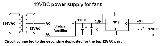 Schematic |
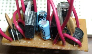 The circuit board, sans protection diodes. |
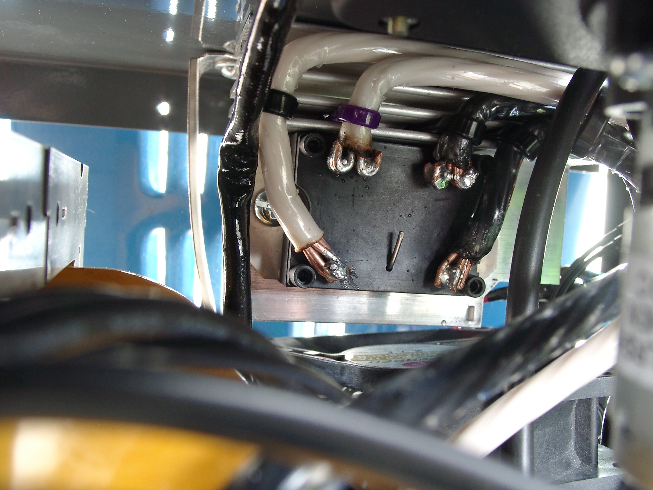
The bridge rectifier was mounted to an aluminum heatsink from another bad power supply. The third pair of diodes for the third phase was left unconnected. Because the pins on the device were small and fragile compared to the 6 gauge wire I was connecting it to, I needed a way to secure the heavy wire so that it wouldn't twist or bend the rectifier's pins. By drilling holes in the heatsink, the wires could be zip tied to the heatsink to prevent them from moving relative to the rectifier. To held solder them without heating the rectifier up excessively, the wire ends were heated with a torch prior to soldering.
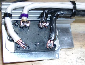 The bridge rectifier mounted and soldered. |
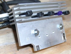 The back of the heatsink. |
About this time, I received the capacitors and discovered that I could only fit two in the case easily. However, I figured 46,000uF would be sufficient for this welder. To connect them, I built a pair of busbars out of 1/4" copper tubing. I started by pounding the tube flat except for a little under 1/2" on one end. I then drilled holes near the ends of the flattened tube for the capacitor terminal screws to go through. I put the end of some 6 gauge wire in the open end of the tube and pounded it flat to crimp it, and then heated the end with a torch to solder it. After slipping some heat shrink tubing over the middle part, the busbars were ready to be mounted to the capacitors. A 150 ohm 10W resistor was also mounted between the capacitor terminals, but this turned out to be too much power to dissipate, so a 160 ohm 7W resistor was added in series to it. These bleeder resistors slowly discharge the capacitors after the welder is switched off. The RC constant for this arrangement is (150 + 160) * 0.046 = 14.26 seconds, and 5RC works out to be 71.3 seconds, so it should take about 1 minute to bring the capacitors to near 0V.
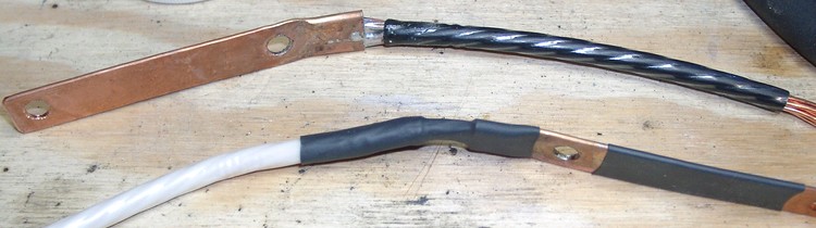 The busbars. |
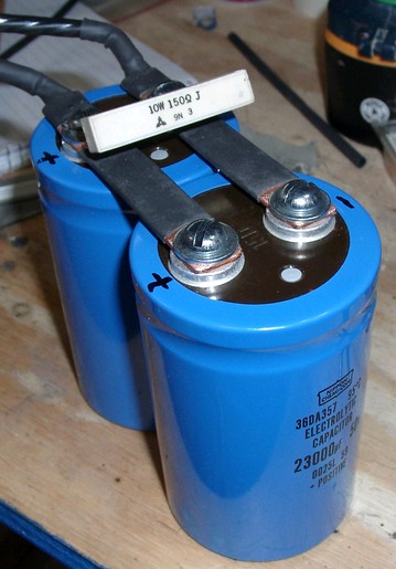 The capacitor bank. |
Mounting everything was a bit of a challenge due to my choice of 6 gauge wire. It's overkill given the short runs, but once I started, I figured I'd continue doing all the wiring the same way. The final connection between the rectifier, capacitor bank, and output terminals was a big connection. I fit a short section of 1/2" copper pipe over the wire ends to crimp the connections, then heated it with a torch to solder it all together. The large heat shrink tubing is from Harbor Freight. I had bought it some time ago, not realizing how large it was until I got home. I never thought I'd use it.
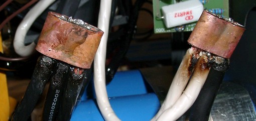 Connections crimped with 1/2" copper pipe. |
Everything worked fine and nothing burned or blew up when I first turned it on, which was a big relief to me. After the first test weld, two things were noticable. First, the initial arc striking seemed to spatter more, probably due to the higher starting voltage and the capacitor bank (42VDC nominal). Second, the weld penetration was greatly improved. Previously, simple T-joints were weak and could be broken if welded only on one side and bent in the weak direction. After the conversion to DC, I could hammer the T-joints in both directions and the weld would easily hold, preferring to bend above the weld.
I tried hooking my digital voltmeter up during a weld as a test, and the DC voltage seemed to center around 15-16VDC with a short stickout and near maximum wire speed. I don't know what's normal during welding, but this didn't seem bad.
Overall, it was an interesting project, and a little more difficult than anticipated. It wouldn't have been much more to buy a welder that was already DC, but that wouldn't have been as fun ;-)
More pictures, click to enlarge:
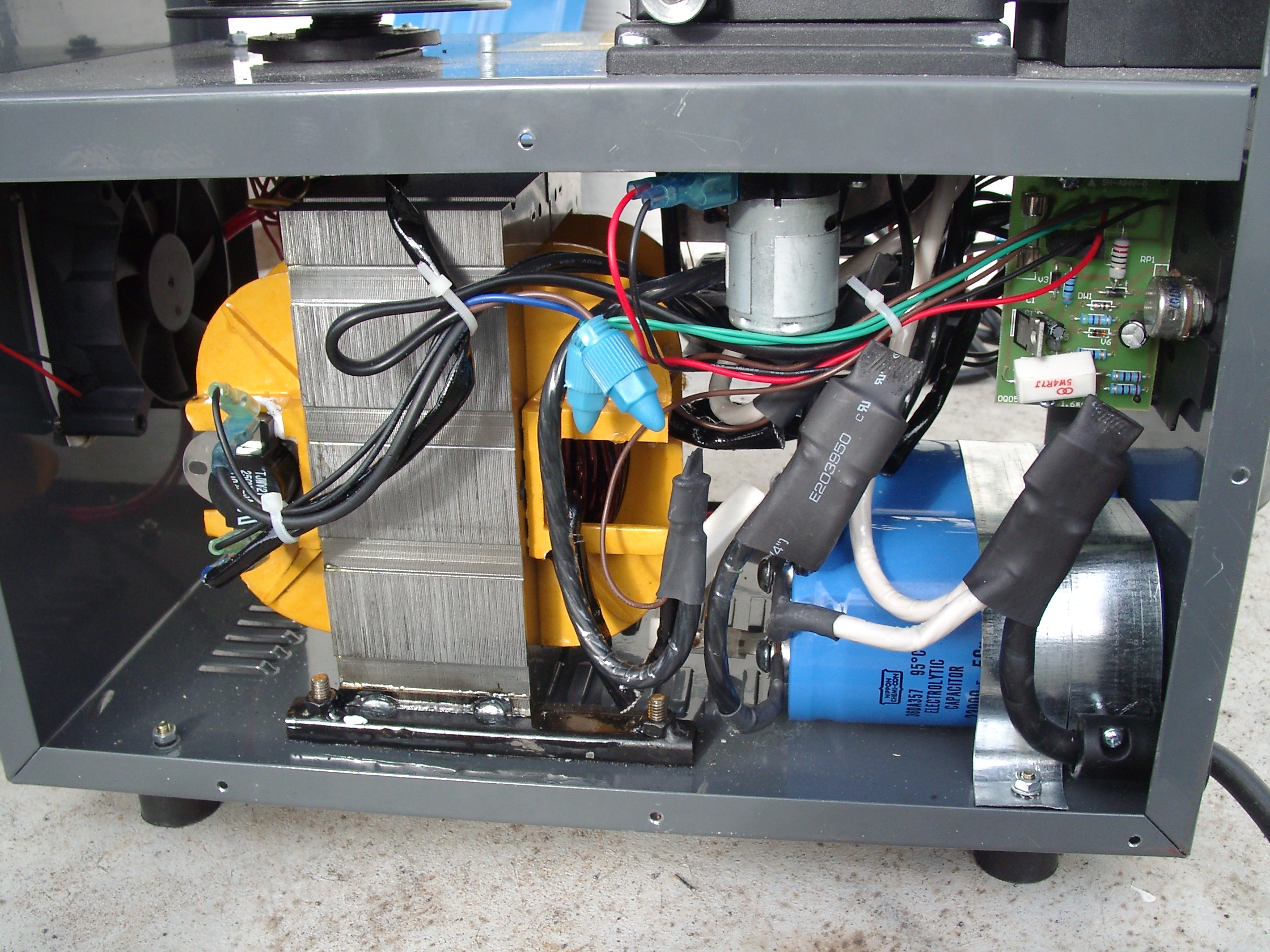 The left side of the welder. |
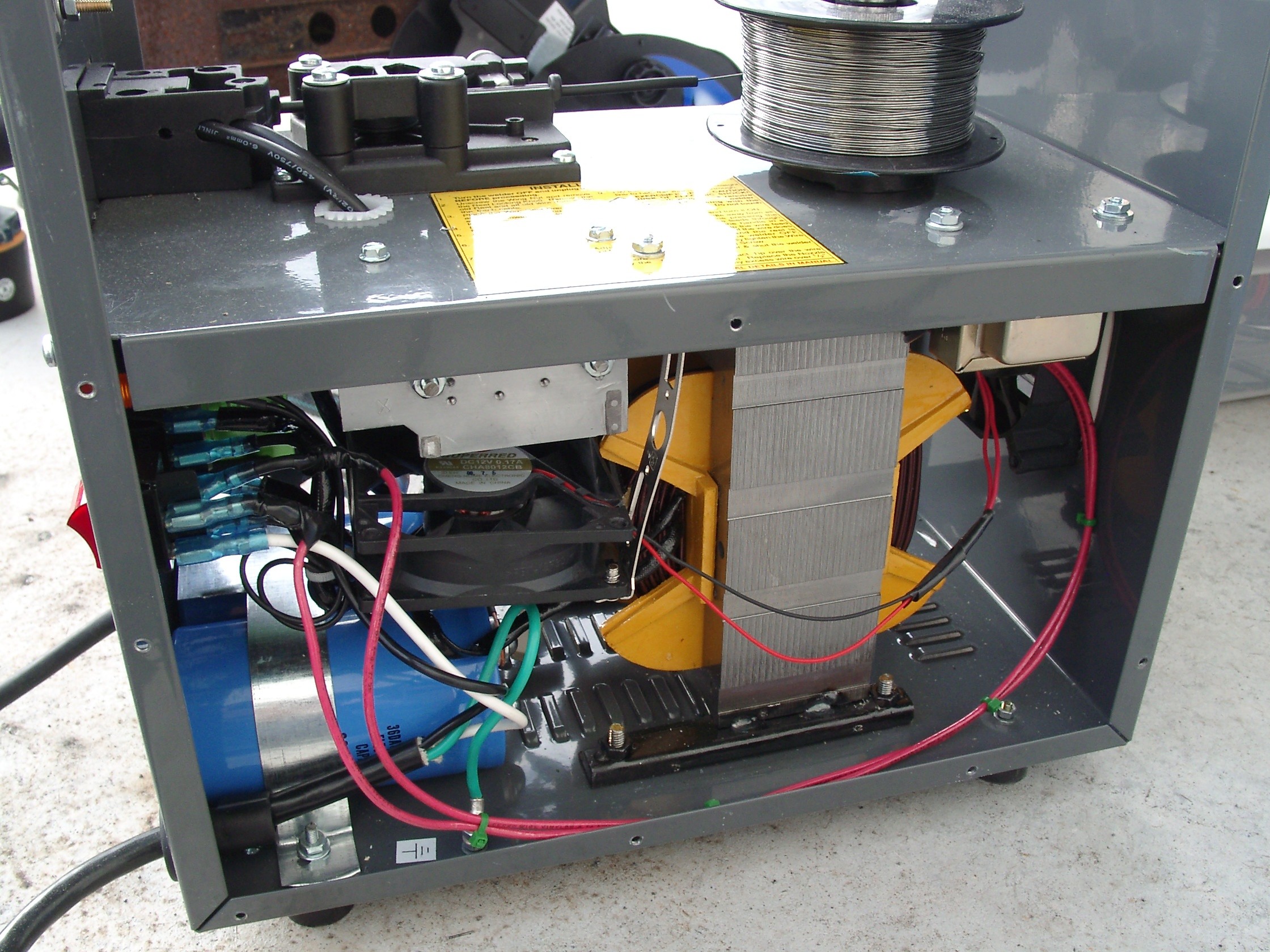 The right side of the welder. |
 Capacitor bank. |
 Rectifier. |
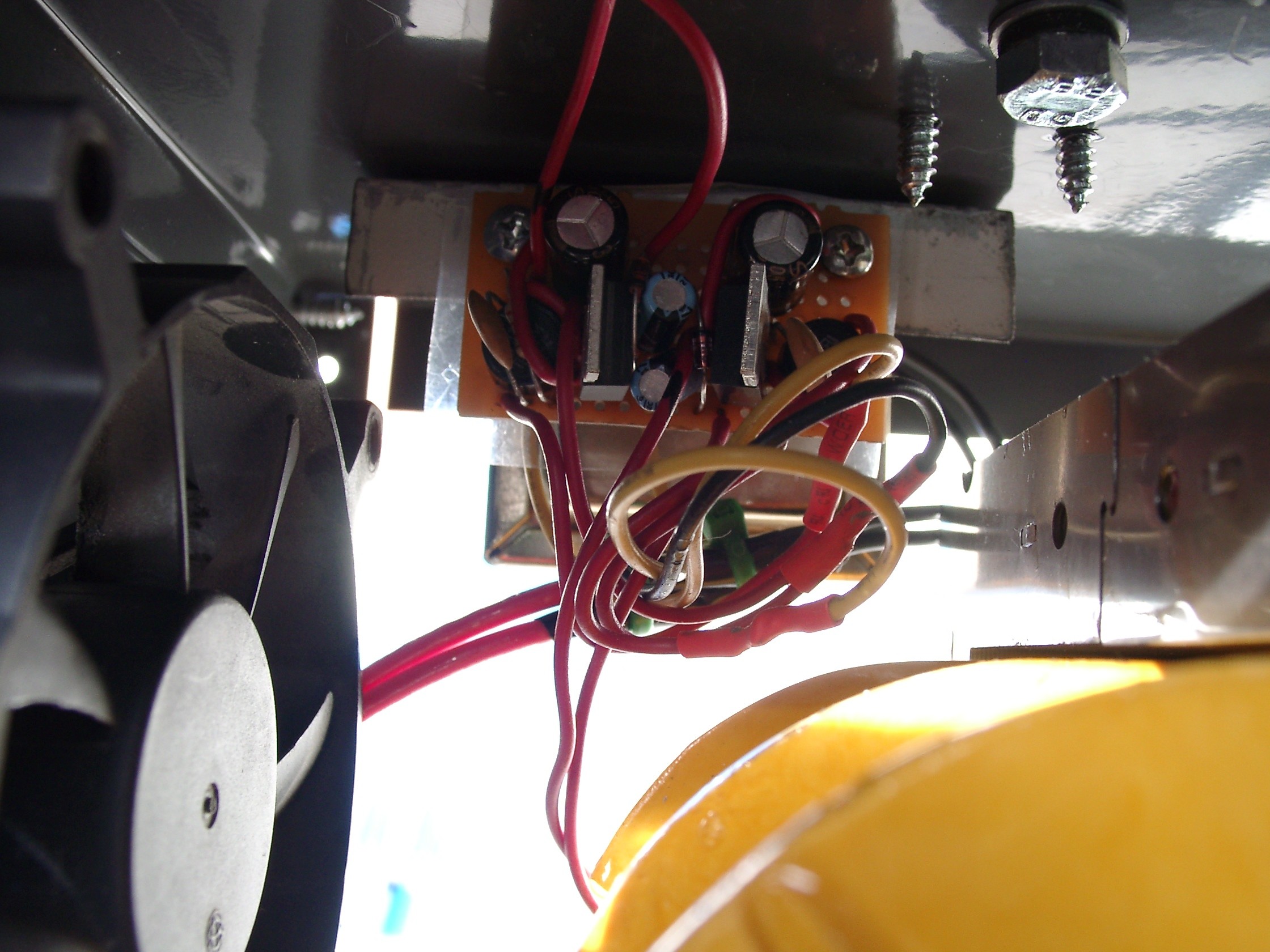 Fan PSU. |
Transformer for the fan PSU. |